Specification-driven functional verification with Verilog PLI & VPI and SystemVerilog DPI

Suraj N. Kurapati

Abstract

Verilog-through its Programming Language Interface (PLI) and Verilog Procedural Interface (VPI)-and SystemVerilog-through its Direct Programming Interface (DPI)-enable simulators to invoke user-defined C functions, which then verify some aspect of an instantiated Verilog or SystemVerilog design.
This simulator-centric transfer of control inhibits specification-driven functional verification, where an executable specification verifies a design firsthand by progressively (1) applying a stimulus to the design, (2) simulating the design by temporarily transferring control to the simulator, and (3) verifying the design's response to the applied stimulus.
This thesis presents (1) a way to achieve specification-driven functional verification with Verilog PLI & VPI and SystemVerilog DPI; (2) a technique that eliminates unnecessary code coupling between a design and its executable specification; and (3) an application of these ideas using Verilog VPI and the Ruby programming language.

Contents

1  Motivation
    1.1  Agile practices in hardware development
    1.2  Simulation-based functional verification
2  Problem
    2.1  Problems with simulator-driven approach
        2.1.1  Dislocation of power
        2.1.2  Communications overhead
        2.1.3  Re-entrant C functions
    2.2  Reason for simulator-driven approach
3  Solution
    3.1  Separate call stacks
        3.1.1  Separation through POSIX threads and semaphores
        3.1.2  Emulation through explicit finite state machines
4  Related works
    4.1  Design-driven approaches
        4.1.1  Co-simulation with cycle-accurate emulator
    4.2  Simulator-driven approaches
        4.2.1  Co-simulation of Verilog and System C
    4.3  Specification-driven approaches
5  Application with Ruby-VPI
    5.1  Overview
    5.2  Motivation
        5.2.1  Leveling up
        5.2.2  Irony of the system task
        5.2.3  Reading and writing integers
        5.2.4  Verbosity of expression
        5.2.5  Appeasing the simulator
    5.3  Organization
        5.3.1  Tests
            5.3.1.1  Automated test generation
        5.3.2  Interface to VPI
            5.3.2.1  Handles
            5.3.2.2  Accessing a handle's relatives
            5.3.2.3  Accessing a handle's properties
        5.3.3  Interaction with Verilog
    5.4  Mechanics
        5.4.1  Execution of a test
        5.4.2  Transfer of control
        5.4.3  Seamless prototyping
    5.5  Usage
        5.5.1  Start with a design
        5.5.2  Generate a test
        5.5.3  Specify your expectations
        5.5.4  Prototype the design
        5.5.5  Verify the prototype
        5.5.6  Implement the design
        5.5.7  Verify the design
6  Evaluation
    6.1  Proposed solution
        6.1.1  Contribution
    6.2  Ruby-VPI project
        6.2.1  Contribution
7  Conclusion
    7.1  Future work
A  Background
    A.1  Reason for PLI, VPI, and DPI interfaces
    A.2  Functional verification
        A.2.1  Simulator-driven functional verification
        A.2.2  Design-driven functional verification
        A.2.3  Specification-driven functional verification
    A.3  Inter-process communication
        A.3.1  Asynchronous communication
            A.3.1.1  Shared memory
            A.3.1.2  Parallel Virtual Machine
            A.3.1.3  Message Passing Interface
        A.3.2  Synchronous communication
            A.3.2.1  Remote Procedure Call
            A.3.2.2  Distributed Common Object Model
            A.3.2.3  Remote Method Invocation
            A.3.2.4  Common Object Request Broker Architecture
        A.3.3  Graphical programming
        A.3.4  Conclusions
    A.4  Agile practices
        A.4.1  Test driven development
        A.4.2  Behavior driven development
    A.5  Domain specific languages
        A.5.1  Alternatives
    A.6  Ruby programming language
        A.6.1  Object oriented
        A.6.2  Anytime processing
        A.6.3  Scripting language
        A.6.4  A platform for DSLs
        A.6.5  On the rise
B  Glossary
    B.1  Tight coupling
    B.2  Executable specification
    B.3  System tasks and functions
    B.4  Callbacks
        B.4.1  Self-generative callbacks

List of Figures

    2.1  Call stack shared by a simulator and the user-defined C function it invokes. The times marked along the horizontal axis correspond to the following events:
    3.1  Illustration of call stacks separated through POSIX threads and semaphores. Here, the simulator runs in the main process, while the specification runs inside a POSIX thread. Shading denotes that a call stack is currently paused due to a locked semaphore. The times marked along the horizontal axis correspond to the following events:
    3.2  VPI application, based on [file rbpli.c]KH99, that enables specification-driven functional verification by running the specification within a POSIX thread.
    3.3  An expectation written for specification-driven functional verification.
    3.4  An expectation written for emulated specification-driven functional verification. Note that a single invocation of the function shown in figure 3.3 is logically equivalent to three continuous invocations of the function shown here.
    5.1  Organization of a test in Ruby-VPI.
    5.2  Ruby expression that determines whether all registers associated with a module presently have an integer value greater than one.
    5.3  C expression that determines whether all registers associated with a module presently have an integer value greater than one.
    5.4  Using the automated test generator.
    5.5  C program that causes a "type mismatch" error in some compilers.
    5.6  Accessors and their implications.
    5.7  Method naming format for accessing a handle's properties.
    5.8  Primary means of control transfer from Ruby to Verilog. This diagram should be read from left to right, according to the following sequence of events:
    5.9  Declaration of a simple up-counter with synchronous reset.
    5.10  Generating a test with specification in RSpec format.
    5.11  Generating a test with specification in xUnit format.
    5.12  A specification that implements the expectations listed in section 5.5.3 using the RSpec specification format.
    5.13  A specification that implements the expectations listed in section 5.5.3 using the xUnit specification format.
    5.14  Ruby interface to the design under verification. The method shown here resets the design by asserting its reset signal, simulating it for one clock cycle, and then deasserting its reset signal.
    5.15  A Ruby prototype of the Verilog design under verification. When prototyping is enabled, Vpi::advance_time invokes the method shown here instead of transferring control to the Verilog simulator.
    5.16  Implementation of a simple up-counter with synchronous reset.
    5.17  Verifying the prototype of the design under verification with the specification implemented in RSpec format.
    5.18  Verifying the prototype of the design under verification with the specification implemented in xUnit format.
    A.1  Invoking a method on an integer in Ruby.

Dedication

To my parents, the source and substratum of my being. vandanamulu.


Acknowledgments

Thank you, one and all.

Chapter 1
Motivation

1.1  Agile practices in hardware development

Moore's law states that "the number of transistors on a chip doubles about every two years" [41]. The complexity of hardware designs undertaken has grown accordingly, leading to increased development time, cost, and effort. This trend is especially evident in design verification, as it "consumes about 70% of the design effort" [4,page 2] and "is increasingly becoming a bottleneck in the design of embedded systems and system-on-chips (SoCs)" [13].
As a result, it has long become common for design firms to house a dedicated team of verification engineers, who often outnumber implementation engineers by a factor of two [4,page 2]. However, this division of labor is unfavorable when viewed in the light of agile software development practices (see section A.4), which improve quality and reduce development time [19] by having the same engineers perform verification alongside implementation.
This thesis proposes an infrastructure that facilitates the application of agile software development practices to the hardware development process (see chapter 5). This infrastructure builds atop Ruby: a general purpose, purely object oriented language that is ideal for rapid prototyping, design automation, and systems integration (see section A.6).

1.2  Simulation-based functional verification

"Simulation has been, and continues to be, the primary method for functional verification of hardware and system level designs" [13]. Simulation-based Hardware Verification Languages (HVLs) such as e, Vera, and Specman have become popular in recent years. However, like Verilog and SystemVerilog, they lack the power of general purpose programmability necessary to integrate the verification effort with other business processes.
For example, the results of an automated verification suite may need to be integrated with project planning and management tools to improve estimates of project completion or to locate particularly troublesome areas of the design to which more verification effort must be allocated. For this reason, C language interfaces like Verilog PLI are often the practical choice for simulation-based functional verification.
Over the decades, Verilog PLI has evolved into simpler, more powerful interfaces such as Verilog VPI and SystemVerilog DPI. However, despite this evolution, these interfaces continue to facilitate the simulator-driven approach to functional verification (see chapter 2). This thesis explores possible ways to achieve the more logical approach of specification-driven functional verification for Verilog PLI & VPI and SystemVerilog DPI (see chapter 3).

Chapter 2
Problem

Verilog-through its Programming Language Interface (PLI) and Verilog Procedural Interface (VPI)-and SystemVerilog-through its Direct Programming Interface (DPI)-enable simulators to invoke user-defined C functions. By inserting code that functionally verifies certain aspects of an instantiated Verilog module into these C functions, one can functionally verify Verilog modules whilst leveraging the general purpose programmability of the C language.
Because (1) the simulator invokes the user-defined C functions and (2) the user-defined C functions perform functional verification, the simulator is in charge of the functional verification process. Having the simulator in charge of functional verification is called simulator-driven functional verification.
This chapter explores the problems associated with the simulator-driven approach and the technical reasons for its existence.

2.1  Problems with simulator-driven approach

2.1.1  Dislocation of power

The main problem with simulator-driven functional verification is that the power to perform functional verification is placed at the wrong level. To better illustrate this claim, consider the following scenario:
A dog house must be built for your new dog. The necessary materials have been provided to you: a hammer, nails, wooden boards, and a blueprint for the dog house.
The hammer in placed in charge. It will summon you to perform tasks on its behalf, such as nailing wooden boards together, verifying that the dog house is being built according to the blueprint, and so on.
Here, the task of building a dog house represents the task of performing functional verification, the blueprint represents the specification, and the hammer represents the simulator.
This scenario is both unpleasant and counter-intuitive because the power to build the dog house has been placed at the wrong level: the hammer is but a mere tool, whose sole purpose is to drive nails; it is unconcerned with the larger task of building a dog house. Thus, the more logical approach would be to grant you the power to build the dog house because you are (1) genuinely concerned with the task of building a dog house and (2) capable of utilizing all provided materials firsthand, whereas the hammer required you to perform tasks on its behalf.
Likewise, the simulator is but a mere tool, whose sole purpose is to simulate an instantiated Verilog module, that is unconcerned with the larger task of performing functional verification. Thus, the more logical approach would be to grant you the power to perform functional verification. However, due to the overwhelming complexity of hardware designs undertaken today, it is both impractical and error-prone for a human to perform functional verification manually. For this reason, executable specifications-which are, in essence, a combination of the blueprint (the rules for building a dog house) and yourself (the entity capable of following the blueprint and interacting with all provided materials to build the dog house)-are commonly used to perform functional verification instead.

2.1.2  Communications overhead

The dislocation of power in simulator-driven functional verification causes additional communications overhead between the simulator and the executable specification because the simulator continually summons the executable specification to perform tasks on its behalf.
To illustrate, recall the scenario presented in the previous section: every time the hammer needs to perform a task, it summons you to perform the task on its behalf. Here, the act of the hammer summoning you represents the additional communications overhead between the simulator and the executable specification.

2.1.3  Re-entrant C functions

Recall that in simulator-driven functional verification, the simulator invokes user-defined C functions to perform functional verification on its behalf. This approach causes the code inside the user-defined C functions to be written in a re-entrant fashion. When written in this fashion, inherently sequential code becomes unnecessarily complex due to the explicit management of states and transitions thereof.
For instance, observe how the inherently sequential code shown in figure 3.3 becomes unnecessarily complex, as shown in figure 3.4, when written in a re-entrant fashion.

2.2  Reason for simulator-driven approach

  
masters_thesis_fig_call_stack.png
Figure 2.1: Call stack shared by a simulator and the user-defined C function it invokes. The times marked along the horizontal axis correspond to the following events:
  1. Simulator has control.
  2. Simulator invokes a user-defined C function, foo. Now foo has control.
  3. foo possibly invokes another function, bar, which may in turn invoke yet another function, and so on.
  4. bar returns along with the other functions it possibly invoked. Now foo has control.
  5. foo returns. Now the simulator has control.
Verilog PLI & VPI and SystemVerilog DPI enable simulator-driven functional verification because (see figure 2.1) when the simulator invokes a user-defined C function, they share a common call stack [35,page 4] in which the simulator's stack frame lies immediately below the function's stack frame.
Due to this arrangement, the simulator cannot proceed until the function returns. Likewise, the function cannot make the simulator proceed without itself having returned. Thus, Verilog PLI & VPI and SystemVerilog DPI place the simulator in charge of performing functional verification and thereby enable the simulator-driven approach.

Chapter 3
Solution

Recall that in simulator-driven functional verification, the simulator invokes user-defined C functions to perform functional verification on its behalf. This dislocation of power causes the rest of the problems associated with simulator-driven functional verification. Thus, these problems can be eliminated by allocating the power to perform functional verification at an appropriate level, i.e. the executable specification.
Having the executable specification in charge of performing functional verification is called specification-driven functional verification. In this approach, an executable specification verifies a design firsthand by progressively (1) applying a stimulus to the design, (2) simulating the design by temporarily transferring control to the simulator, and (3) verifying the design's response to the applied stimulus.
Section 3.1 proposes technical solutions for achieving specification-driven functional verification with Verilog PLI & VPI and SystemVerilog DPI.

3.1  Separate call stacks

As section 2.2 discussed, we are restricted to simulator-driven functional verification with Verilog PLI & VPI and SystemVerilog DPI because the stack frames of a simulator and the C function it invokes, exist within the same call stack. Therefore, one solution is to provide separate call stacks for these stack frames. In practice, however, this is only possible if a simulator and C function exist either within (1) different threads or (2) different processes.
Placing the simulator and executable specification in different threads, which exist within the same process, allows the specification to access its design naturally through the C library provided by Verilog PLI & VPI and SystemVerilog DPI. In contrast, placing them in either (1) different processes or (2) different threads within different processes, necessitates IPC (see section A.3) as the specification cannot access to the aforementioned C library directly.
The threads approach is simpler and more practical than the processes approach because invoking C functions within a single process is trivial in comparison to the relatively monumental task of deploying and managing independent processes in a distributed simulation through IPC. For this reason, only the threads approach is considered henceforth.

3.1.1  Separation through POSIX threads and semaphores

masters_thesis_fig_separate_stacks.png
Figure 3.1: Illustration of call stacks separated through POSIX threads and semaphores. Here, the simulator runs in the main process, while the specification runs inside a POSIX thread. Shading denotes that a call stack is currently paused due to a locked semaphore. The times marked along the horizontal axis correspond to the following events:
  1. Simulator has control.
  2. Simulator transfers control to the specification by invoking the relay_spec function shown in figure 3.2.
    1. Simulator is paused.
    2. Specification has control.
  3. Specification possibly invokes other functions.
  4. Specification has control.
  5. Specification transfers control to the simulator by invoking the relay_sim function shown in figure 3.2.
    1. Specification is paused.
    2. Simulator has control.
  6. Simulator possibly invokes other functions.
  7. Simulator has control.
  8. Steps 2-7 repeat until the verification process is complete.
#include <stddef.h>
#include <pthread.h>
#include <vpi_user.h>

void* spec_run(void* dummy) {
  /* 1. schedule a callback to relay_spec();
     2. invoke relay_sim();
     3. repeat */
  return NULL;
}

pthread_t specThread;
pthread_mutex_t specLock;
pthread_mutex_t simLock;

PLI_INT32 relay_init(p_cb_data dummy) {
  pthread_mutex_init(&specLock, NULL);
  pthread_mutex_lock(&specLock);
  pthread_mutex_init(&simLock, NULL);
  pthread_mutex_lock(&simLock);

  /* start the specification thread */
  pthread_create(&specThread, NULL, spec_run, NULL);
  pthread_mutex_lock(&simLock);

  return 0;
}

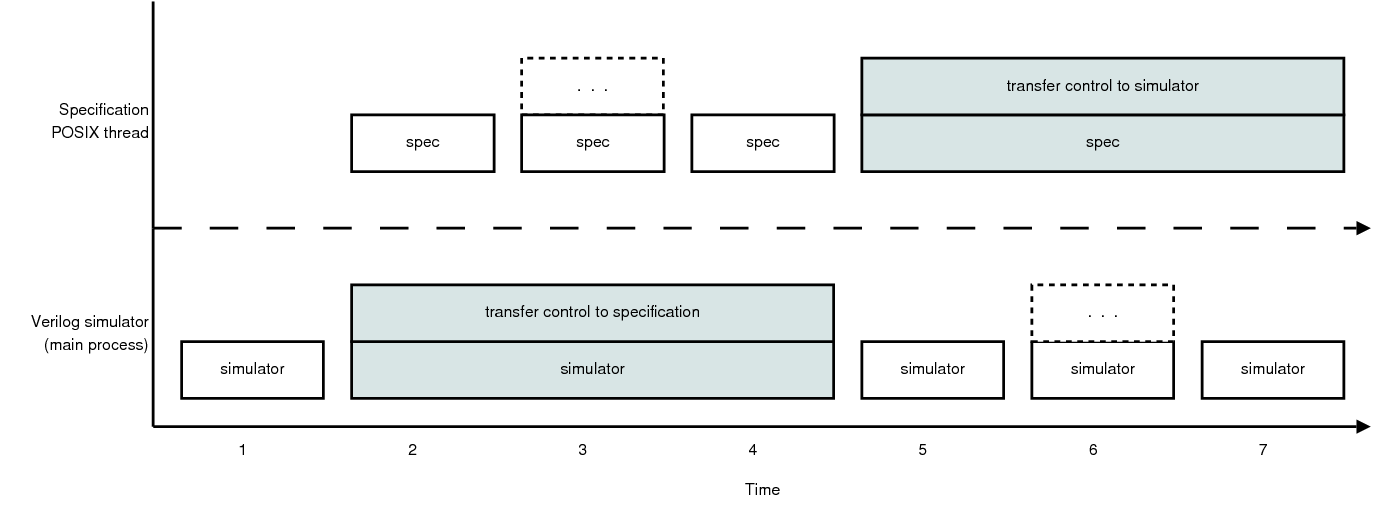
/* Transfers control to the specification. */
void relay_spec() {
  pthread_mutex_unlock(&specLock);
  pthread_mutex_lock(&simLock);
}

/* Transfers control to the Verilog simulator. */
void relay_sim() {
  pthread_mutex_unlock(&simLock);
  pthread_mutex_lock(&specLock);
}

void startup() {
  s_cb_data call;
  call.reason     = cbStartOfSimulation;
  call.cb_rtn     = relay_init;
  call.obj        = NULL;
  call.time       = NULL;
  call.value      = NULL;
  call.user_data  = NULL;

  vpi_free_object(vpi_register_cb(&call));
}

void (*vlog_startup_routines[])() = { startup, NULL };

Figure 3.2: VPI application, based on , that enables specification-driven functional verification by running the specification within a POSIX thread.
The call stacks of simulator and specification can be separated through POSIX threads and semaphores as follows:
The separation achieved by this approach is illustrated in figure 3.1. In addition, the source code in figure 3.2 demonstrates how this approach can be implemented with Verilog VPI.
In this source code, the startup function is first invoked by a Verilog simulator because its function pointer is present within the vlog_startup_routines array [18,page 374]. This function schedules a callback that invokes the relay_init function just before the simulation begins.
When the relay_init function is invoked, it initiates a series of self-generative callbacks1 by running the specification within a POSIX thread. This thread endlessly (1) executes for some time, (2) transfers control to the Verilog simulator, and (3) regains control from the Verilog simulator. In particular, it regains control by scheduling a callback to the relay_spec function before transferring control to the Verilog simulator. Later, this callback causes the Verilog simulator to transfer control to the specification.
The process of transferring control to and regaining control from a simulator can be encapsulated by a function within the specification. For instance, the simulate_design function in figure 3.3 serves this exact purpose.

3.1.2  Emulation through explicit finite state machines

void verify_expectation() {
  apply_stimulus();
  simulate_design();
  verify_response();
}

Figure 3.3: An expectation written for specification-driven functional verification.
void verify_expectation() {
  static enum {
    stimulate, 
    simulate, 
    verify
  } stage = stimulate;

  switch (stage) {
    case stimulate:
      apply_stimulus();
      stage = simulate;
      break;

    case simulate:
      simulate_design();
      stage = verify;
      break;

    case verify:
      verify_response();
      stage = stimulate;
      break;
  }
}

Figure 3.4: An expectation written for emulated specification-driven functional verification. Note that a single invocation of the function shown in figure 3.3 is logically equivalent to three continuous invocations of the function shown here.
It is possible to emulate the separation of call stacks by having the specification remember from where within its source code it had last transferred control to the simulator. This allows specification to resume execution from its previous location when it regains control from the simulator.
As figure 3.4 shows, emulation is achieved by writing the specification and its expectations as finite state machines. However, this style of writing is unnatural and laborious because (1) it involves transforming an otherwise simple sequence of steps into an explicit finite state machine; and because (2) tight coupling is naturally present between each pair of adjacent states in these particular finite state machines.
If Verilog PLI & VPI and SystemVerilog DPI truly enabled specification-driven functional verification, a specification and its expectations could be written naturally, with less effort, as illustrated by figure 3.3.

Chapter 4
Related works

Several related works are presented in the following subsections. Although these works do not particularly tackle the problem of how to achieve specification-driven functional verification with Verilog PLI & VPI and SystemVerilog DPI, their contributions have been characterized as such for the sake of discussion.

4.1  Design-driven approaches

[8] presents Cadence TestBuilder, a C++ library built atop Verilog PLI that enables executable specifications to be written in C++. Unfortunately, this library takes the design-driven approach to functional verification because it requires explicit (1) initialization of the executable specification via the $tbv_main system task and (2) transfer of control from the simulator to the executable specification via Verilog's behavioral wait statement [8,page 5].

4.1.1  Co-simulation with cycle-accurate emulator

[23] speeds up the simulation of a complex Verilog design by having an emulator perform part of the simulation. It achieves this by implementing IPC over network sockets through Verilog PLI system tasks to transmit the stimulus to and receive the response from the emulator.

4.2  Simulator-driven approaches

[43] enables potential customers to functionally verify proprietary Verilog designs whilst protecting proprietary interests through Verilog PLI and IPC over network sockets. In this approach, the customer's executable specification is written in behavioral Verilog-which is considered unsuitable for verification (see section A.1). Nevertheless, this approach is novel because the details of the IPC are hidden from both the executable specification and the proprietary design alike by automatically generated shell modules-modules which simply wrap other modules, occasionally along with additional functionality.

4.2.1  Co-simulation of Verilog and System C

In United States Patent 20030093584, RPC is used through Verilog PLI to connect a Verilog module to a behavioral System C module. This allows the Verilog module to interact with the remote System C module as if they both existed in the same simulation. However, this approach is still an example of simulator-driven functional verification because the executable specification is either written in behavioral Verilog or in C through the PLI.

4.3  Specification-driven approaches

[1] presents a verification framework, named Raven, that enables specification-driven functional verification with generic logic simulators of RTL and gate-level HDL designs. In Raven, executable specifications are written in C++ using a library named Diagnostic Programming Interface (DPI), and the executable specification and the logic simulator communicate via IPC over network sockets. Raven was used to verify a "1.1 million gate ASIC that routes packetized messages on the interconnection network of a scalable multiprocessor" and was found to have a 10% performance penalty, due to the overhead of IPC, over a standard Verilog test-bench [1,page 168].
Some criticisms of [1] are that it fails to specify (1) which particular logic simulators were successfully used with Raven and (2) what must be done to make a logic simulator service the IPC requests sent from Raven's executable specification. That is, there is no mention of any technologies-such as such as Verilog PLI or VPI-that allow programs capable of servicing IPC requests to be used with the RTL and gate-level HDL designs that Raven is supposed to accommodate. Instead, [1] simply presents (1) data-type primitives used to represent Verilog logic values in C++ and (2) the application-level protocol used for Raven's IPC, whilst omitting any details about their implementation.

Chapter 5
Application with Ruby-VPI

This chapter presents an application of the separation of call stacks through POSIX threads and semaphores solution (see section 3.1.1) using Verilog VPI and the Ruby programming language. In particular, this application is realized through an open source software package named Ruby-VPI (see [21]).


masters_thesis_fig_organization_detailed.png
Figure 5.1: Organization of a test in Ruby-VPI.

5.1  Overview

Ruby-VPI is a bridge between IEEE 1364-2005 Verilog VPI and the Ruby language. It enables Ruby programs to use VPI either (1) in the same, verbose way that C programs do, or (2) in a simpler, higher level way. In addition, it serves as a vehicle for the application of agile software development practices, such as TDD and BDD, to the realm of hardware development with Verilog.
Ruby-VPI can be used with any Verilog simulator that supports VPI. In particular, it known to operate with (1) Synopsys VCS and Mentor Modelsim, the two most prominent Verilog simulators in the Electronic Design Automation (EDA) industry [12]; as well as (2) GPL Cver and Icarus Verilog, the two most prevalent open source Verilog simulators of today.
As figure 5.1 shows, Ruby-VPI is composed of two complementary parts: one interacts with VPI through the C language, while the other interacts with an executable specification written in the Ruby language. The former is complied during installation to produce dynamically loadable C libraries-each tailored to accommodate the quirks of its respective Verilog simulator (see section 5.2.5). The latter is not compiled because Ruby programs are interpreted dynamically.

5.2  Motivation

C code. C code run. Run code run. Please! -Cynthia Dunning
The drudgery of using VPI through the C programming language and VPI's inherent dependence on simulator-driven functional verification were the primary factors that motivated the creation of Ruby-VPI. These factors, among others, are discussed in the following subsections.

5.2.1  Leveling up

Advancement to higher level languages is a proved strategy for managing the ever-increasing complexity of software. In fact, it has been said to yield "at least a factor of five in productivity, and with concomitant gains in reliability, simplicity, and comprehensibility" [6,page 15]. But how can such advancement-a mere change of notation-possibly procure such remarkable benefits? The answer is that a higher level language "frees a program from much of its accidental complexity" [6,page 15].
For instance, consider the power notation in mathematics where a base is raised to the power of an exponent: 22048. This is a higher level way of writing the expression "2×2" two thousand and forty eight consecutive times: \underset20482×2×…2. Were it not for such notation, the expression of thought would be far more laborious, repetitive, and erroneous. In this manner, higher level programming languages are notations that enable us to reason abstractly using sufficient notation to swiftly express, entertain, and dispose of the problem at hand. In other words [6,page 15]:
An abstract program consists of conceptual constructs: operations, data types, sequences, and communication. The concrete machine program is concerned with bits, registers, conditions, branches, channels, disks, and such. To the extent that the high-level language embodies the constructs one wants in the abstract program and avoids all lower ones, it eliminates a whole level of complexity that was never inherent in the program at all.
This argument strongly motivates and justifies the use of a higher level language, such as Ruby, in performing functional verification with Verilog VPI.

5.2.2  Irony of the system task

Quis custodiet ipsos custodes? -Juvenal, Satires, VI, 346-348
A system task is composed of two C functions: calltf and compiletf [36,page 34 and 39]. The former is invoked whenever its associated system task is invoked, and the latter is invoked, only once, before the simulation begins [36,page 37].
Whereas the calltf function defines verification logic for a system task, the sole purpose of the compiletf function is to verify that its system task, and thereby its associated calltf function, is invoked correctly [36,page 37]. For example, it checks whether (1) the number of arguments passed to its system task, and (2) the types of those arguments are correct [36,page 37].
This situation resembles the ancient, recursive dilemma quis custodiet ipsos custodes? or who guards the guardians? by which, the compiletf function procures a mere illusion of increased correctness while inadvertently sacrificing ease of development, as compiletf functions must be written and maintained alongside every system task that performs verification.

5.2.3  Reading and writing integers

Integers in VPI are 32 bits wide, as defined by the portable PLI_INT32 storage type [18,page 522][36,page 163]. Due to this constraint, reading and writing the integer value of a register, whose width is larger than 32 bits, requires additional processing.
For instance, one might process the string representation of the register's integer value in an incremental, piecewise fashion by transforming a subset of the string into an integer or vice versa. Another option is to write or use a library that encapsulates this process by providing integer operations that act upon strings. Nevertheless, the integer/string conversion involved in this process introduces the following accidental difficulties.
Memory management  
To avoid tight coupling (see section B.1) between one's C program and Verilog design, one might dynamically allocate buffers for use during the integer/string conversion. However, one must now ensure that (1) the memory occupied by those buffers are freed after the transformation, and that (2) one stays within the bounds of the buffers during their use. Otherwise, memory leaks and buffer-overrun vulnerabilities may occur, respectively.
Tight coupling  
To avoid the difficulties of memory management or performance penalties [36,page 161] of dynamic memory allocation, one might use fixed-length buffers, which are explicitly sized to accommodate the widths of registers in the Verilog design, during the integer/string conversion. However, this arrangement is tightly coupled (see section B.1) because a change in register width necessitates an analogous change in buffer size.

5.2.4  Verbosity of expression

He draweth out the thread of his verbosity finer than the staple of his argument. -William Shakespeare, Love's Labour's Lost, 5:1
Because the C programming language is a high level language, i.e. one level of abstraction higher than assembler, it seems verbose in comparison to very high level languages such as Ruby. This verbosity of expression necessitates increased effort to perform even the most basic of tasks.
For example, consider the expressions shown in figures 5.2 and 5.3. Both determine whether all registers associated with a module, whose handle is stored in the some_module variable, presently have a logic value that is greater than one when accessed in integer form. The result of each expression is ultimately stored in the result variable.
Notice how the Ruby expression captures the intent of our task in a clear, concise manner. It seems to read out loud: "the result is whether some module has all registers such that each register has an integer value greater than one". In contrast, the C expression mechanically orchestrates our task, more so than reflecting our intent, in painstaking detail. It seems to drone: "assume result true; declare local variables; iterate over registers; read integer value; check integer value; adjust result; free iterator..." ad nauseam.
result = some_module.all_reg? {  - reg -  reg.intVal > 1 }
Figure 5.2: Ruby expression that determines whether all registers associated with a module presently have an integer value greater than one.
int result = 1; /* true */

s_vpi_value wrapper;
vpiHandle reg;
vpiHandle iterator = vpi_iterate( vpiReg, some_module );

while (reg = vpi_scan( iterator )) {
  wrapper.format = vpiIntVal;
  vpi_get_value( reg, wrapper );

  if (wrapper.value.integer <= 1) {
    result = 0; /* false */
    vpi_free_object( iterator );
    break;
  }
}

Figure 5.3: C expression that determines whether all registers associated with a module presently have an integer value greater than one.

5.2.5  Appeasing the simulator

Not all Verilog simulators adhere to the VPI specification. For instance, whereas [18,page 522] defines user-defined system tasks and functions as having the form:
PLI_INT32 foo ( PLI_BYTE8* );
Synopsys VCS, one of the two most prominent Verilog simulators in use today [12], ignores them unless they are written in the form:
void foo ( void );
Therefore, in order to maintain portability across different Verilog simulators, one must appease them conditionally through the #ifdef directive of the C preprocessor.

5.3  Organization

Being an agile programming language, Ruby naturally facilitates agile software development practices such as TDD and BDD. Furthermore, since Ruby-VPI augments Ruby with the IEEE 1364-2005 Verilog VPI, it extends the reach of these agile software development practices to the otherwise unreachable realm of hardware development.
To better facilitate the application of agile practices to hardware development, Ruby-VPI follows the convention over configuration [40] philosophy with respect to the organization and performance of functional verification. This philosophy promotes the provision of "sensible defaults" [40,page 37], which allow specifications to be "written using little or no external configuration-things just knit themselves together in a natural way" [40,page 37].
The following subsections discuss the conventions posed by Ruby-VPI.

5.3.1  Tests

In Ruby-VPI, the process of functional verification is neatly packaged into self-contained, executable tests. As figure 5.1 illustrates, a test is composed of a bench, a design, and a specification.
The bench defines the environment in which functional verification takes place. It is analogous to a workbench in an electronics laboratory that is furnished with tools of measurement and manipulation such as oscilloscopes, voltmeters, soldering irons, and so on. These tools enable engineers to verify electronic components and locate the source of defects within those components.
The design is an instantiated Verilog module. To extend the analogy of the electronics laboratory, it corresponds to the electronic component that is verified by an engineer.
The specification is a Ruby program. In the electronics laboratory analogy, it corresponds to the engineer who inspects, manipulates, and verifies the electronic component. In terms of specification-driven functional verification, it corresponds to the executable specification.

5.3.1.1  Automated test generation

$ generate_test.rb foo.v --name bar

  module  foo
  create  foo_bar_runner.rake
  create  foo_bar_bench.v
  create  foo_bar_bench.rb
  create  foo_bar_design.rb
  create  foo_bar_proto.rb
  create  foo_bar_spec.rb

Figure 5.4: Using the automated test generator.
Ruby-VPI provides a tool, known as the automated test generator, which generates tests from Verilog module declarations (see figure 5.4) that adhere to the syntax defined by [17,pages 762-763] or [18,page 487]. A generated test is composed of the following files:
runner.rake
runs the test by executing a Verilog simulator with Ruby-VPI.
bench.v
instantiates the Verilog module being verified.
bench.rb
bootstraps the test by loading the design, prototype, and specification.
design.rb
provides a Ruby interface to the Verilog module being verified.
proto.rb
defines a Ruby prototype of the Verilog module being verified.
spec.rb
the executable specification for the Verilog module being verified.
As figure 5.4 shows, the name of each generated file is prefixed with (1) the name of the Verilog module for which the test was generated and (2) a user-defined identifier for the test. This convention helps organize tests within the file system, so that they are readily distinguishable from one another.
By producing multiple files, the automated test generator physically decouples the various parts of a test. As a result, when the interface of a Verilog module changes, you can simply regenerate the test to incorporate those changes without diverting your focus from the task at hand. Furthermore, the incorporation of changes can be catalyzed by interactive text merging tools, which allow you to selectively accept or reject the merging of changes into your source code. Fully automated text merging tools may also be used for this purpose.

5.3.2  Interface to VPI

Ruby-VPI makes the entire IEEE Std 1364-2005 VPI interface available to Ruby, but with the following minor differences.
Names are capitalized  
The names of all VPI types, structures, and constants become capitalized because Ruby requires that the names of constants begin with a capital letter. For example, the s_vpi_value structure becomes the S_vpi_value class in Ruby. Likewise, the vpiIntVal constant becomes the VpiIntVal constant in Ruby.
However, Ruby's capitalization rule does not apply to VPI functions; their names appear in Ruby just as they do in C.
Use Ruby's printf  
#include <stdarg.h>
void foo(va_list ap) {
  va_list *p = &ap;
}

Figure 5.5: C program that causes a "type mismatch" error in some compilers.
The VPI functions vpi_vprintf and vpi_mcd_vprintf are not made accessible to Ruby because some C compilers have trouble with pointers to the va_list storage type. For example, these compilers emit a type mismatch error upon encountering the third line of the source code shown in figure 5.5. For this reason, you are advised to use Ruby's printf method, which is functionally equivalent to its C counterpart, instead.

5.3.2.1  Handles

A handle is a reference to an object-such as a module, register, wire, and so on-inside the Verilog simulation. Handles allows you to inspect and manipulate the design under verification and its internal components. They are instances of the Vpi::Handle class in Ruby-VPI.
AccessorKind of value accessedVPI functions used to access the value
ddelayvpi_get_delays and vpi_put_delays
llogicvpi_get_value and vpi_put_value
iintegervpi_get
bbooleanvpi_get
sstringvpi_get_str
hhandlevpi_handle
Figure 5.6: Accessors and their implications.
Handles have various properties, listed in the second column of table 5.6, which provide different kinds of information about the underlying Verilog objects they represent. These properties are accessed through the VPI functions listed in the last column of said table.
Handles are typically obtained through the vpi_handle_by_name and vpi_handle functions. These functions are hierarchical in nature, as they allow you to obtain new handles that are related to existing ones. For example, to obtain a handle to a register contained within a module, one would typically write:
some_reg = vpi_handle( VpiReg, some_handle )
Shortcuts for productivity  
Given a handle, Ruby-VPI allows you to access (1) its relatives and (2) its properties simply by invoking methods on the handle. If a handle's relative happens to have the same name as one its properties, then the relative is given priority because a handle's properties can always be accessed explicitly through the handle.get_value and handle.put_value methods.

5.3.2.2  Accessing a handle's relatives

Imagine that the design under verification, say foo, instantiated a Verilog module named bar, which in turn contained a register named baz. To access baz from Ruby, one could employ VPI idioms by writing:
foo = vpi_handle_by_name( "foo", nil )
bar = vpi_handle_by_name( "bar", foo )
baz = vpi_handle_by_name( "baz", bar )
or by writing:
baz = vpi_handle_by_name( "foo.bar.bar", nil )
These idioms seem excessively verbose in a higher level language such as Ruby, so Ruby-VPI allows you to access a handle's relative by simply invoking the relative's name as a method on the handle:
foo.bar.baz

5.3.2.3  Accessing a handle's properties

Imagine that the design under test, say foo, contained a register named bar. To access the integer value of bar in Ruby-VPI, one could employ VPI idioms by writing:
wrapper = S_vpi_value.new
wrapper.format = VpiIntVal
vpi_get_value( foo.bar, wrapper )
result = wrapper.value.integer
or, if bar is capable of storing more than 32 bits, one would convert a string representation of bar's integer value into a limitless2 Ruby integer by writing:
wrapper = S_vpi_value.new
wrapper.format = VpiHexStrVal
vpi_get_value( foo.bar, wrapper )
result = wrapper.value.str.to_i( 16 )
These idioms seem excessively verbose in a higher level language such as Ruby, so Ruby-VPI allows you to access a handle's properties by simply invoking property names, using the special naming format shown in figure 5.7, as methods on the handle:
result = foo.bar.intVal
Operation_Property_AccessorAddendum
optionalrequiredoptional
Figure 5.7: Method naming format for accessing a handle's properties.
Operation
specifies a method that should be invoked within the context of the Property parameter. All methods in Ruby's Enumerable module are valid operations.
Property
suggests a VPI property that should be accessed. The vpi prefix, which is common to all VPI properties, can be omitted if you wish. For example, the VPI property vpiFullName is considered equivalent to fullName and FullName, but not equivalent to full_name.
Accessor
suggests a VPI function that should be used in order to access the VPI property. When this parameter is not specified, Ruby-VPI will attempt to guess its value. Table 5.6 shows a list of valid accessors and how they influence the means by which a property is accessed.
Addendum
suggests that the specified VPI property should be written to, when the value of this parameter is an equal sign (=).

In addition, when the value of this parameter is a question mark (?), it suggests that the specified VPI property should be accessed as a boolean value. This suggestion is the same as specifying b for the Accessor parameter.
Examples  
To better understand the method naming format shown in figure 5.7, consider the following examples. Each example lists a set of equivalent Ruby expressions which access the value of a handle's property and, in some cases, perform an operation with that value.
handle.vpiIntVal
handle.vpiIntVal_l
handle.intVal
handle.intVal_l
handle.vpiIntVal   = 2 ** 2048
handle.vpiIntVal_l = 2 ** 2048
handle.intVal      = 2 ** 2048
handle.intVal_l    = 2 ** 2048
handle.vpiType
handle.vpiType_i
handle.type
handle.type_i
handle.vpiProtected
handle.vpiProtected_b
handle.vpiProtected?
handle.protected
handle.protected_b
handle.protected?
handle.vpiFullName
handle.vpiFullName_s
handle.fullName
handle.fullName_s
handle.vpiParent
handle.vpiParent_h
handle.parent
handle.parent_h 
handle.each_vpiNet  {  - net -  puts net.fullName }
handle.each_net     {  - net -  puts net.fullName }
handle.each(VpiNet) {  - net -  puts net.fullName }
handle[VpiNet].each {  - net -  puts net.fullName }
handle.all_vpiReg?  {  - reg -  reg.size == 1 }
handle.all_reg?     {  - reg -  reg.size == 1 }
handle.all?(VpiReg) {  - reg -  reg.size == 1 }
handle[VpiReg].all? {  - reg -  reg.size == 1 }

5.3.3  Interaction with Verilog

A specification simulates the Verilog design by invoking the Vpi::simulate method. This method is vaguely named because its semantics depend on the particular design being verified. The task of defining those semantics is given to the bench.rb file since it is responsible for defining the environment for functional verification. It achieves this task by passing a block of code to the RubyVpi::init_bench method, which then executes that block whenever Vpi::simulate is invoked.

5.4  Mechanics

Ruby-VPI employs the technique discussed in section 3.1.1 to enable specification-driven functional verification. However, the details differ slightly because in Ruby-VPI, executable specifications are written in Ruby rather than in C. These differences are discussed in the following subsections.

5.4.1  Execution of a test

When a test runner runs a test (see section 5.3.1), it invokes a Verilog simulator along with a precompiled shared-object file provided by Ruby-VPI. This file contains a particular definition of the vlog_startup_routines array that schedules a callback to be executed just before the start of the simulation.
Upon execution, this callback starts a Ruby interpreter within a POSIX thread. The interpreter begins processing the test's bench.rb file, which loads the remaining Ruby source files that belong to the test and then initiates execution of the specification. Once the specification functionally verifies the Verilog design, the Ruby interpreter, its containing POSIX thread, and the Verilog simulator exit in succession.

5.4.2  Transfer of control

masters_thesis_fig_ruby_relay.png
Figure 5.8: Primary means of control transfer from Ruby to Verilog. This diagram should be read from left to right, according to the following sequence of events:
  1. The specification has control.
  2. The current simulation time is x.
  3. The specification invokes the Vpi::advance_time method with parameter y, which specifies the number of simulation time steps to be simulated. This method temporarily transfers control from Ruby to the Verilog simulator.
  4. The Verilog simulator has control.
  5. The current simulation time is still x.
  6. The Verilog simulator simulates y simulation time steps.
  7. The current simulation time is now x+y.
  8. The Verilog simulator returns control back to the specification.
The primary means of control transfer from the Ruby interpreter to the Verilog simulator is the Vpi::advance_time method shown in figure 5.8.
The secondary means of control transfer is the callback. Callbacks are scheduled in Ruby in much the same way as they are in C. The only difference is that instead of storing the address of a C function in the cb_rtn field of the s_cb_data structure-as you would do in C-you pass a block of code to the vpi_register_cb method in Ruby. This block will then be executed whenever the callback occurs.

5.4.3  Seamless prototyping

Ruby-VPI enables rapid prototyping where one can model the behavior of Verilog designs purely in Ruby. This process is wholly transparent: there is absolutely no difference, in terms of the executable specification's implementation, between the functional verification of a real Verilog design or its Ruby prototype. Furthermore, prototypes exhibit their artificial behavior using nothing more than the VPI itself.
For example, compare the Verilog design shown in figure 5.16 with its Ruby prototype shown in figure 5.15. The prototype uses only VPI to (1) detect changes in its inputs and (2) manipulate its outputs accordingly. In addition, notice how well the prototype's syntax reflects the intended behavior of the Verilog design. This similarity facilitates rapid translation of a prototype from Ruby into Verilog later in the design process.
Activation  
Prototyping is enabled by setting the PROTOTYPE environment variable to a non-empty value, as demonstrated in figures 5.17 and 5.18. Likewise, it is disabled by either (1) setting the PROTOTYPE environment variable to an empty value or (2) un-setting the variable altogether.
Mechanism  
The Vpi::advance_time method normally transfers control to the Verilog simulator. However, when prototyping is enabled, it invokes the simulate! method, which is defined in a test's proto.rb file, instead. This method artificially simulates the behavior of the real Verilog design.
In this manner, control is kept within the Ruby interpreter when prototyping is enabled. An advantage of this approach is that it reduces the total execution time3 of a Ruby-VPI test by allowing Ruby's POSIX thread to commandeer the Verilog simulator's process. A disadvantage of this approach is that callbacks, which require the transfer of control to the Verilog simulator, must be ignored.

5.5  Usage

This section presents a guide that illustrates how Ruby-VPI is commonly used. This guide is composed of the following steps, which are discussed in more detail in subsequent sections.
  1. Start with a design you want to verify.
  2. Generate a test for your design using the automated test generator.
  3. Identify your expectations about the design.
  4. Add your expectations to the executable specification.
  5. Run the test to functionally verify your design.
  6. Change your design's source code so that it satisfies any failed expectations.
  7. Repeat steps 3-6 as necessary.
This sequence of steps lends itself to the iterative style of development, emphasized in the agile practices of TDD and BDD, because it can be performed iteratively as follows:
  1. Choose one expectation to verify.
  2. Add the expectation to the executable specification.
  3. Verify the design against the executable specification.
  4. Change the design's source code so that it satisfies any failed expectations.
  5. Repeat steps 1-4 until you are satisfied.

5.5.1  Start with a design

First, we need a design to functionally verify. In this guide, the Verilog module shown in figure 5.9 will serve as our design.
module counter #(parameter Size = 5) (
  input clock,
  input reset,
  output reg [Size - 1 : 0] count
);
endmodule

Figure 5.9: Declaration of a simple up-counter with synchronous reset.
Its interface is composed of the following parts:
Before we continue, save the source code shown in figure 5.9 into a file named counter.v.

5.5.2  Generate a test

Now that we have a design to verify, let us generate a test for it using the automated test generator. This tool allows us to implement our specification in either RSpec, xUnit, or our very own format:
Once we have decided how we want to implement our specification, we can proceed to generate a test for our design. This process is illustrated by figures 5.10 and 5.11.
$ generate_test.rb counter.v --rspec --name rspec

  module  counter
  create  counter_rspec_runner.rake
  create  counter_rspec_bench.v
  create  counter_rspec_bench.rb
  create  counter_rspec_design.rb
  create  counter_rspec_proto.rb
  create  counter_rspec_spec.rb

Figure 5.10: Generating a test with specification in RSpec format.
$ generate_test.rb counter.v --xunit --name xunit

  module  counter
  create  counter_xunit_runner.rake
  create  counter_xunit_bench.v
  create  counter_xunit_bench.rb
  create  counter_xunit_design.rb
  create  counter_xunit_proto.rb
  create  counter_xunit_spec.rb

Figure 5.11: Generating a test with specification in xUnit format.

5.5.3  Specify your expectations

So far, the test generation tool has created a basic foundation for our test. Now we must build upon this foundation by identifying our expectation of the design. That is, how do we expect the design to behave under certain conditions?
Here are some reasonable expectations for our simple counter:
Now that we have identified a set of expectations for our design, we are ready to implement them in our specification. Figures 5.12 and 5.13 show how our expectations would appear after being implemented in the RSpec and xUnit specification formats respectively. Notice the striking similarity between these specifications: they differ in syntax but appear identical otherwise.
# tight upper bound for counter's value
LIMIT = 2 ** Counter.Size.intVal

# maximum allowed value for a counter
MAX = LIMIT - 1

context "A resetted counter's value" do
  setup do
    Counter.reset!
  end

  specify "should be zero" do
    Counter.count.intVal.should == 0
  end

  specify "should increment upon rising clock edges" do
    LIMIT.times do |i|
      Counter.count.intVal.should == i
      simulate # increment the counter
    end
  end
end

context "A counter with the maximum value" do
  setup do
    Counter.reset!

    # increment the counter to maximum value
    MAX.times { simulate }
    Counter.count.intVal.should == MAX
  end

  specify "should overflow upon increment" do
    simulate # increment the counter
    Counter.count.intVal.should == 0
  end
end

Figure 5.12: A specification that implements the expectations listed in section 5.5.3 using the RSpec specification format.
# tight upper bound for counter's value
LIMIT = 2 ** Counter.Size.intVal

# maximum allowed value for a counter
MAX = LIMIT - 1

class ResettedCounterValue < Test::Unit::TestCase
  def setup
    Counter.reset!
  end

  def test_zero
    assert_equal 0, Counter.count.intVal
  end

  def test_increment
    LIMIT.times do |i|
      assert_equal i, Counter.count.intVal
      simulate # increment the counter
    end
  end
end

class MaximumCounterValue < Test::Unit::TestCase
  def setup
    Counter.reset!

    # increment the counter to maximum value
    MAX.times { simulate }
    assert_equal MAX, Counter.count.intVal
  end

  def test_overflow
    simulate # increment the counter
    assert_equal 0, Counter.count.intVal
  end
end

Figure 5.13: A specification that implements the expectations listed in section 5.5.3 using the xUnit specification format.
def Counter.reset!
  reset.intVal = 1
  simulate
  reset.intVal = 0
end

Figure 5.14: Ruby interface to the design under verification. The method shown here resets the design by asserting its reset signal, simulating it for one clock cycle, and then deasserting its reset signal.
Before we continue,
  1. Replace the contents of the file named counter_rspec_spec.rb with the source code shown in figure 5.12.
  2. Replace the contents of the file named counter_xunit_spec.rb with the source code shown in figure 5.13.
  3. Replace the contents of the files named counter_rspec_design.rb and counter_xunit_design.rb with the source code shown in figure 5.14.

5.5.4  Prototype the design

Now that we have a specification against which to verify our design, let us build a prototype of our design. By doing so, we exercise our specification, experience potential problems that may arise when we later implement our design in Verilog, and gain confidence in our work. However, note that prototyping is wholly optional; the main aim of Ruby-VPI is to allow functional verification of real Verilog modules, not of mere behavioral prototypes.
def Counter.simulate!
  if clock.posedge?
    if reset.intVal == 1
      count.intVal = 0
    else
      count.intVal += 1
    end
  end
end

Figure 5.15: A Ruby prototype of the Verilog design under verification. When prototyping is enabled, Vpi::advance_time invokes the method shown here instead of transferring control to the Verilog simulator.
module counter #(parameter Size = 5) (
  input clock,
  input reset,
  output reg [Size - 1 : 0] count
);
  always @(posedge clock) begin
    if (reset)
      count <= 0;
    else
      count <= count + 1;
  end
endmodule

Figure 5.16: Implementation of a simple up-counter with synchronous reset.
Figure 5.15 shows an example prototype for our design. Before we continue, replace the contents of the files named counter_rspec_proto.rb and counter_xunit_proto.rb with the source code shown this figure.

5.5.5  Verify the prototype

$ rake -f counter_rspec_runner.rake cver PROTOTYPE=1

Ruby-VPI: prototype has been enabled for test "counter_rspec" 

A resetted counter's value
- should be zero
- should increment upon rising clock edges

A counter with the maximum value
- should overflow upon increment

Finished in 0.018199 seconds

3 specifications, 0 failures

Figure 5.17: Verifying the prototype of the design under verification with the specification implemented in RSpec format.
$ rake -f counter_xunit_runner.rake cver PROTOTYPE=1

Ruby-VPI: prototype has been enabled for test "counter_xunit" 

Loaded suite counter_xunit_bench
Started
...
Finished in 0.040668 seconds.

3 tests, 35 assertions, 0 failures, 0 errors

Figure 5.18: Verifying the prototype of the design under verification with the specification implemented in xUnit format.
Now that we have implemented our prototype, we are ready to verify it against our specification by running the test. This process is illustrated by the figures 5.17 and 5.18.
In these figures, the PROTOTYPE environment variable is assigned a non-empty value while running the test so that, rather than our design, our prototype is verified against our specification. You may also assign a value to PROTOTYPE before running the test through your shell's export or setenv command. Finally, the GPL Cver simulator, denoted by cver, is used to run the simulation.

5.5.6  Implement the design

Now that we have implemented and verified our prototype, we are ready to implement our design. This is often quite simple as we can translate existing code from our Ruby prototype into our Verilog design. For instance, notice the similarity between the implementation of our design, shown in figure 5.16, and its prototype, shown in figure 5.15.
Before we continue, replace the contents of the file named counter.v with the source code shown in figure 5.16.

5.5.7  Verify the design

Now that we have implemented our design, we are ready to verify it against our specification by running the test. This process is identical to the one used in verifying our prototype (see section 5.5.5) except that the PROTOTYPE environment variable is not specified while running the test. This ensures that our design, rather than our prototype, is verified against our specification.

Chapter 6
Evaluation

6.1  Proposed solution

The proposed solution of separating call stacks through the use of POSIX threads and semaphores has been successfully implemented for Verilog VPI in both (1) figure 3.2 and (2) the Ruby-VPI project.
Although implementations of this solution for Verilog PLI and SystemVerilog DPI have not been presented in this thesis, they would be very similar in nature to that of Verilog VPI. In particular, the only major difference between implementations would be the use of different programming interfaces: Verilog PLI would be used for the Verilog PLI solution, and SystemVerilog DPI would be used for the SystemVerilog DPI solution.

6.1.1  Contribution

The proposed solution is based on , which uses VPI system tasks to transfer control between the simulator and the executable specification, and thereby employs the design-driven approach to functional verification.
My primary contribution to this solution is transforming the design-driven approach of into a specification-driven approach by eliminating tight coupling between the design and the executable specification through the use of self-generative callbacks.

6.2  Ruby-VPI project

The primary goal of Ruby-VPI was to provide a way to functionally verify Verilog modules using a unit testing framework-in the same way that software modules are functionally verified. In short, this goal would provide the means to apply agile software development practices, such as TDD and BDD, to the realm of RTL-based hardware development with Verilog.
The secondary goal of Ruby-VPI was to provide a way to rapidly prototype the functionality of Verilog modules in Ruby without having to first implement them in full using Verilog. This would allow for quicker prototyping because implementing a Verilog module in full typically requires more effort than emulating the module's behavior in Ruby (see section 5.5.5).
Both goals have been accomplished successfully.

6.2.1  Contribution

In October 1999, Japanese researcher Kazuhiro Hiwada pioneered the technique of separating the stack frames of the Verilog simulator and the specification through POSIX threads and semaphores. He released this work, as a proof of concept, under the name Ruby-VPI (see [15]). It enabled one to execute a predefined Ruby program from within a Verilog module through the use of predefined VPI system tasks. However, that was the extent of its capability; it provided neither (1) the means to pass parameters from Verilog to the Ruby program nor (2) a means to access VPI from within Ruby.
Seven years later, in February 2006, I happened upon Hiwada's work while searching for Ruby bindings to Verilog PLI or VPI in order to simplify the task of writing a fairly complex Verilog test bench. I augmented his work with the ability to (1) pass parameters from Verilog to Ruby and (2) access the Verilog module under test through a minuscule subset of VPI. Next, I attempted to contact him, in hopes of contributing my additions, but failed to locate a more recent means of communication than an obsolete e-mail address listed on his old (circa 1999) website. Alas, it seemed that Ruby-VPI was genuinely abandoned, so I decided to revive it in the form of an open source4 software project.
Over the course of a year, I developed Ruby-VPI into a stable, functional platform for specification-driven functional verification. My notable contributions include (1) the addition of the ability to access the entire IEEE 1364-2005 Verilog VPI from within Ruby, (2) the decoupling of the Verilog design from the specification through the self-generative callbacks technique, (3) the production and maintenance of a comprehensive user manual, and (4) integration with unit testing frameworks (xUnit and RSpec), interactive debuggers (ruby-debug), code coverage analyzers (RCov), and build automation tools (Rake).

Chapter 7
Conclusion

Although specification-driven functional verification is not enabled by Verilog PLI & VPI and SystemVerilog DPI, it can be achieved nevertheless by separating the call stacks of the simulator and the C function it invokes. At present, this separation is only possible by running the simulator and executable specification within (1) different threads or (2) different processes. In terms of ease of implementation and maintenance effort, the former approach is the simpler of the two.
Ruby-VPI lifts the burden of using Verilog VPI in the C programming language by enabling engineers to functionally verify Verilog designs at a very high level. Raising the level of abstraction allows engineers to focus on the problem at hand rather than struggling with low level details [6]. Furthermore, Ruby-VPI brings agile development practices, such as TDD and BDD, to the otherwise inapplicable realm of hardware development.

7.1  Future work

The method of separating the simulator and the executable specification through the use of POSIX threads and semaphores may be applied in enabling specification-driven functional verification with very high level languages other than Ruby, such as Python, Lisp, and Smalltalk.
Ruby-VPI can be extended to simplify other verification tasks through DSLs. Transaction-based verification (see [5]) is one problem domain where such DSLs might prove useful. This form of verification is better known as Transaction Level Modeling (TLM) in the realm of Electronic System Level (ESL) design-an industry primarily concerned with the integration of hardware and embedded software. In this domain, a Ruby-based DSL would offer a higher level of abstraction than what System C-the most popular DSL in the ESL domain [12]-is capable, due to the latter's heritage of low level expression from the C programming language.
 

Appendix A
Background

A.1  Reason for PLI, VPI, and DPI interfaces

Verilog is considered unsuitable for verification because it lacks features, such as high-level data structures [4,page 55], that are "important in efficiently implementing a modern verification process" [4,page 55]. The Programming Language Interface (PLI) and Verilog Procedural Interface (VPI) counterbalance this limitation by augmenting Verilog with the full power and capability of the C programming language.
SystemVerilog, on the other hand, is considered suitable for verification because it "is able to raise the level of abstraction compared to plain Verilog" [4,page 55] by offering, among other features, high-level data structures and object-oriented constructs [4,page 56]. Nevertheless, the Direct Programming Interface (DPI) augments SystemVerilog with the full power and capability of the C programming language.
These interfaces enable simulators to invoke user-defined C functions:
They also serve as a C library that enables invoked C functions to inspect and modify objects in instantiated designs [18,page 376] with varying degrees of capability: VPI offers the most and DPI offers the least, while PLI offers a balance between the two [35,pages 14-15].

A.2  Functional verification

Functional verification is the process of determining whether a design satisfies a specification [13,page 1][4,page 1] composed of one or more expectations [2,00:13:09-00:13:24].
An expectation is a statement that specifies (1) a scenario and (2) the expected behavior of a design placed in that scenario [2,00:32:01-00:32:12]. As a result, expectations are naturally expressed in terms of stimulus and response [4,page 30]. For instance, one might say "when the design is subjected to condition X (the stimulus), it should behave in manner Y (the response)".
A design is systematically verified for functional correctness by iteratively checking whether it satisfies each expectation in its specification. This check is performed, in accordance to the stimulus and response defined by an expectation, by (1) applying the stimulus to the design and (2) confirming that the design exhibits the expected response.

A.2.1  Simulator-driven functional verification

In simulator-driven functional verification, a simulator invokes C functions-through Verilog PLI & VPI and SystemVerilog DPI-in an executable specification to verify certain aspects of an instantiated Verilog or SystemVerilog design. This simulator-centric approach causes expectations to be written unnaturally, in a discontinuous, piecewise manner because the specification is not in control of verifying its design.
To illustrate, suppose that you (the specification) order a breakfast meal (the design) at a restaurant (the simulator). Instead of serving your meal all at once, this restaurant iteratively serves one subset of your meal at a time. Furthermore, the size of each serving and the delay between servings is unpredictable because you are not in control of your meal. As a result, you are made to eat unnaturally, in a discontinuous, piecewise manner.

A.2.2  Design-driven functional verification

Design-driven functional verification is a subset of simulator-driven functional verification where C functions, in an executable specification, are invoked through system/imported tasks and functions. Since these constructs are statements in a design's source code, the design drives the verification process firsthand and therefore verifies itself.
This approach introduces tight coupling (see section B.1) between a design and its executable specification because changes in either (1) the number of C functions or (2) the names of C functions in the specification necessitate analogous changes to the system/imported tasks and functions in the design's source code.
Self-generative callbacks can eliminate such coupling-if they are initially scheduled by a function whose pointer exists within the vlog_startup_routines array-because unlike system/imported tasks and functions, they do not require modification of a design's source code [26,page 3].

A.2.3  Specification-driven functional verification

In specification-driven functional verification, an executable specification verifies its Verilog design firsthand by progressively (1) applying a stimulus to the design, (2) simulating the design by temporarily transferring control to the simulator, and (3) verifying the design's response to the applied stimulus.
This approach makes a design independent from its specification because changes in the specification do not necessitate changes in the design's source code. It allows expectations to be written naturally, in a continuous, sequential manner as shown in figure 3.3.
In the realm of software development, this approach is better known as unit testing (see [14]) because it encourages a mode of iterative development where each Verilog design (the unit) is functionally verified by its dedicated, personal specification (the test). Moreover, it reflects the traditional way in which Verilog designs were functionally verified [32,pages 81-83], where a design's inputs would be manipulated using a sequence of time-delayed behavioral Verilog statements and its outputs would be recorded onto a text file by (1) printing signal values using $display statements or (2) emitting a waveform in Verilog Change Dump (VCD) format. This recording would then be validated against a golden reference model, which defines how the recording should appear if it is indeed correct, either (1) by manual inspection or (2) through the aid of automated diff tools.

A.3  Inter-process communication

Inter-process communication (IPC) is the mechanism by which (1) processes or (2) threads within different processes communicate with one another. Such communication is necessary in distributed applications where processes, running within different computer systems on a common network, solve problems cooperatively.
Inter-process communication is characterized into two classes: synchronous and asynchronous. The following subsections discuss these classes as well as technologies that enable them.

A.3.1  Asynchronous communication

Asynchronous methods of inter-process communication are well suited for distributed applications involving the computation of independent tasks. For example, consider a distributed business application which retrieves the number of new employees hired every year in the last 50 years. Assuming that the process of retrieving the number of new employees hired in a given year does not depend on that of the previous year, we can distribute the overall calculation across 50 different processes-each of which calculates the number of new employees hired during a single year-and combine their individual results into one suitable for the overall calculation.
Asynchronous methods are error-prone in multi-threaded programming environments [24] due to lack of built-in synchronization facilities, such as semaphores, to prevent communication of obsolete or incorrect data.

A.3.1.1  Shared memory

Before the introduction of message-passing models of asynchronous communication in the late 1970's [20], a technique called "shared memory" was widely in use by supercomputers as a means of inter-process and -processor communication [20]. As the name suggests, this technique involves the reading and writing of data or messages to an area of shared memory.
The disadvantages of this approach are that (1) it does not scale well for distributed applications running on computing clusters [20] and (2) it has synchronization issues such as race conditions-which further complicate a distributed application as semaphores are necessary to mitigate them. In addition, this approach is susceptible to failure as the corruption of the shared memory by a disgruntled process can bring it down, so to speak.
Component Object Model   
Component Object Model (COM) is a shared-memory model of inter-process communication for the Microsoft Windows operating system [24]. It was originally implemented through the "clipboard" facility and provided naming services through the "registry" facility of said operating system [24].
Although the use of COM is widespread in Microsoft Windows based applications, their programming interface can be quite inhibiting. In particular, (1) COM has "no implementation inheritance, thus a component defining a derived interface must implement all functions of the base interfaces again" [24], (2) it is susceptible to failure because the event of a "registry" corruption [24] can render inter-process communication nonfunctional, and (3) it can destabilize the remainder of the operating system [24]. In addition, COM operates on a single processor and does not facilitate communication over a network [24,20].

A.3.1.2  Parallel Virtual Machine

Parallel Virtual Machine (PVM) is a programming interface that allows distributed applications to function over a heterogeneous network composed of (1) machines of different architectures and (2) processes implemented in different programming languages [20,34]. PVM achieves such portability by providing the necessary "message format transformation to hide differences in computer architectures" [20].
PVM is "based on the premise that a collection of independent computer systems, interconnected by networks, can be transformed into a coherent, powerful, and cost-effective concurrent computing resource" [34]. In other words, the aim of PVM is to craft the illusion that a computation is occurring on a single machine [20]. This enables developers to focus on implementing the calculation performed by their distributed application rather than becoming enveloped within the myriad of complexities introduced by low level inter-process communication.
PVM is very dynamic, in the sense that processes and machines can be added to and removed from the distributed computation without having to bring down the entire network [20]. It also provides a naming service, which allows processes to dynamically discover other processes and services without being hard-coded to do so [20]. Lastly, PVM is fault tolerant as it can dynamically detect and send a notice, indicating which computer became faulty, to functional computers [20]. Alternatively, PVM can command a faulty machine to reboot itself-thereby minimizing unavailability of computational resources on the network.

A.3.1.3  Message Passing Interface

Message Passing Interface (MPI) is a programming interface for distributed applications that was originally developed by supercomputer vendors so that their applications could be compatible with each other [20]. It was designed to function over a homogeneous network of processes and processors, allowing it to take advantage of native network calls to make inter-process communication more efficient [20].
MPI provides a powerful library of communication procedures that allow (1) point-to-point communication between two processes and (2) point-to-group communication between a single process and a group of processes [20]. However, due to its reliance on network homogeneity, it cannot function over a network of machines with different architectures or processes implemented in different programming languages.
MPI is static, in the sense that processes and machines cannot be added to and removed from a distributed computation without having to bring down the entire network [20]. Consequently, it does not provide a common naming service that would enable processes and groups of processes to discover each other. Instead, groups and communication paths must be manually allocated before a distributed computation is started. Finally, MPI does not have a failure resolution mechanism to revive faulty machines on the computational network [20].
Despite these shortcomings, MPI goes a step further, in terms of message-passing communication methods, in providing support for seamless communication of derived data-types [20,34]. In other words, one is not strictly limited to primitives-data types that are integral to a programming language, such as an integer, character, or floating-point number-while performing inter-process communication.

A.3.2  Synchronous communication

Synchronous methods of inter-process communication are well suited for distributed applications involving the computation of interdependent tasks. For example, consider a distributed business application which calculates a statistical correlation between the number of new employees hired in a given year with that of the previous year, for each year in the last 50 years. In this situation, we cannot simply delegate the computation onto 50 different processes, which perform independently of each other, and combine their results at the end. Instead, each process must communicate with one that is computing the statistical correlation of the year before that of itself.
In this manner, synchronous communication can become complex as the number dependencies in the functional decomposition of a computation increase.

A.3.2.1  Remote Procedure Call

Remote Procedure Call (RPC), introduced in 1984 [42], is a programming interface allows a process to execute a procedure or routine on a remote processor as if it were executed on its own [24]. It seamlessly encapsulates the synchronous communication necessary to perform procedure calls by automatically transmitting procedure-call arguments and return values [24]. However, only primitive data types may be used in performing remote procedure calls [24,20].
The following subsections describe methods of synchronous communication which are based upon RPC.

A.3.2.2  Distributed Common Object Model

Distributed Common Object Model (DCOM) is a programming interface for the Microsoft Windows operating system [20]. Microsoft describes it as "COM with a long wire" [20] because it adds networking functionality to COM through RPC [20]. It can function across a homogeneous network of processes and heterogeneous network of processors-which run the Microsoft Windows operating system [20].
However, like COM, DCOM utilizes the "registry" facility of said operating system for naming services and is therefore susceptible to failure (see section A.3.1.1).

A.3.2.3  Remote Method Invocation

Remote Method Invocation (RMI), introduced with the Java Developer's Kit 1.1 [42], is a programming interface specific to the Java programming language. It can be thought of as an object-oriented version of RPC which allows an object in one Java Virtual Machine (JVM) to invoke a method on an object within another JVM-be it local or remote [42,33]. In particular, RMI facilitates transparent serialization of objects and entire trees of their references-which allows one to pass complex data-structures, both local and remote [24], as arguments in addition to primitive data-types-and provides a naming service which allows Java objects to discover each other. Also, because the JVM can function on a majority of processor architectures [33,42], RMI can function over a heterogeneous network of processors and homogeneous network of JVM processes.
RMI changes the way developers think about and design distributed applications [42] by introducing the notion of "stubs" and "skeletons", which decouple inter-process communication interfaces-i.e. the interface construct of the Java programming language-from their implementation [42,33]. The term "stub" refers to the interface seen by a Java application that wishes to invoke a remote procedure, while the term "skeleton" refers to the implementation of the stub's Java programming interface [42,33]. When a remote procedure is invoked through the stub's interface, the stub communicates with the skeleton in the remote JVM, thereby performing a remote procedure call [42,33]. In addition, stubs can be downloaded from a remote JVM on demand [24], which makes RMI ideal for dynamic, ad hoc wireless or mobile networks.

A.3.2.4  Common Object Request Broker Architecture

Common Object Request Broker Architecture (CORBA) is a programming interface which functions over a heterogeneous network of processes and processors [20] and, more importantly, is "supported by a large industry consortium" [24]. It centralizes inter-process communication through a primary proxy known as the Object Request Broker (ORB) [20], which separates the implementation of computational procedures-known as "object services" [20]-from their RPC interfaces [20,24].
Like MPI, CORBA is particularly useful for static computational networks, but ill-suited for dynamic ones, such as ad hoc wireless or mobile networks [24].

A.3.3  Graphical programming

In addition to asynchronous and synchronous programming interfaces for implementing distributed applications, there exist graphical methods which allow one to implement "program decomposition, communication primitives (like PVM and MPI calls) and task assignment to network topologies" [20]. In particular, [20] cites a relatively successful project named "GRAPNEL", which implements the aforementioned goals of graphical programming. This project also supports an integrated development environment, named "GRADE" [20], which features a distributed debugger, performance monitor, and visualization tools [20]. However, [34] notes that these graphical systems have not had much main-stream acceptance as methods of inter-process communication.

A.3.4  Conclusions

With the massive transition from low to high level methods of inter-process communication in effect during the last twenty years, it would seem that there is a trend in favor of encapsulating complex system-dependent communication routines [20,24] in standard high level programming interfaces. With the advent of high level methods previously discussed, the creation and management of communication paths between various processes may very well become the next problem-especially in static methods such as MPI and CORBA.
Upcoming graphical programming interfaces seek to facilitate the management of communication paths and resource allocation by allowing one to visually connect processes together. Despite not having received much attention as of yet [34], these methods may prove useful in managing computational networks in the future, as the number of machines available to perform distributed computations increases dramatically over time.

A.4  Agile practices

Big ships turn slowly. -Unknown
Traditional heavy-weight software development practices try to minimize unforeseen changes to a project plan by strictly adhering to precomputed requirements, schedules, and costs [44]. In contrast, agile software development practices embrace and adapt to unforeseen changes as and when they occur [44]. According to [3], these practices have a set of common, underlying characteristics that unify them under the "agile" name [7,page 213]:
We are uncovering better ways of developing software by doing it and helping others do it. Through this work we have come to value:
Individuals and interactions over processes and tools
Working software over comprehensive documentation
Customer collaboration over contract negotiation
Responding to change over following a plan
That is, while there is value in the items on the right, we value the items on the left more.

A.4.1  Test driven development

Test driven development (TDD) is an iterative software development practice that "requires writing automated tests prior to developing functional code in small, rapid iterations" [19,page 43]. In particular, the TDD defines a development process where [19,page 44]:
For every tiny bit of functionality in the production code, you first develop a test that specifies and validates what the code will do. You then produce exactly as much code as will enable that test to pass. Then you refactor (simplify and clarify) both the production code and the test code.
TDD plays a central role, along with pair programming and source code refactoring, in eXtreme Programming (XP)-one of the better known agile software development methodologies [19,page 43].

A.4.2  Behavior driven development

Behavior driven development (BDD) is a subset of TDD which emphasizes thinking in terms of behavior rather than testing [2]. It achieves this primarily through the use of a very specific vocabulary that engages developers, managers, analysts, and entrepreneurs alike [27] in characterizing the desired, or expected, behavior of systems they wish to design, develop, verify, analyze, and finally market. This vocabulary differs from that of TDD. For instance, the TDD terms "test" and "unit" are replaced by "specification" in BDD [2]. Likewise, the TDD notion of "assertion" is replaced by "expectation" in BDD [2].
Due to its focus on characterization and analysis of behavior, BDD plays a more important role in the design process than it does in verification [2].

A.5  Domain specific languages

Unlike general purpose programming languages, Domain Specific Languages (DSLs) are suited for solving a specific family of problems [9] because they allow you to express ideas and think in terms of the issues that pertain to the particular domain of the problem at hand. For example, the Structured Query Language (SQL) is a DSL that facilitates storage, retrieval, and manipulation of data housed within a relational database. In addition, the Starbucks coffee shop DSL: "Venti half-caf, non-fat, no foam, no whip latte" [10,slide 6], and the music conductor's DSL: "Route 66, swinging, easy on the chorus, extra solo at the coda, and bump at the end" [10,slide 6] are more examples.
DSLs are not a new phenomenon; some of today's general purpose programming languages were originally DSLs [9]:
The older programming languages (Cobol, Fortran, Lisp) all came into existence as dedicated languages for solving problems in a certain area (respectively business processing, numeric computation and symbolic processing). Gradually they have evolved into general purpose languages
Despite this evolution, thorough studies of DSLs have only begun in recent years because "over and over again the need for more specialized language support to solve problems in well-defined application domains has resurfaced" [9].

A.5.1  Alternatives

DSLs are often substituted with (1) subroutine libraries and (2) object-oriented and component frameworks [9]. The former provides an interface through which an existing general purpose programming language solves problems in a certain domain. Consequently, it is "the classical method for packaging reusable domain-knowledge" [9]. The latter goes a step further by encapsulating subroutine libraries within a high level framework that directly invokes application-specific code [9].

A.6  Ruby programming language

Sometimes people jot down pseudo-code on paper. If that pseudo-code runs directly on their computers, it's best, isn't it? Ruby tries to be like that, like pseudo-code that runs. -Yukihiro Matsumoto
Ruby is a very high level, general purpose, object oriented programming language invented by Japanese computer scientist Yukihiro Matsumoto in the early 1990's [30,39]. It offers a harmonious balance between the functional and imperative styles of programming by blending the essence of Perl, Smalltalk, Eiffel, Ada, and Lisp [30] into one language. In addition, Ruby is considered to be an agile language because (1) it values programmer productivity over machine efficiency, (2) it aids interpersonal communication through its clear, expressive syntax and high readability, and (3) it is a dynamic language that not only embraces but facilitates change [22,pages 3-8].

A.6.1  Object oriented

Like Smalltalk, Ruby is truly object oriented because everything-including such things as integers, floating point numbers, classes, modules, and methods-is an object in Ruby [30]. For example, invoking the integer fifteen's next method yields the integer sixteen, as illustrated by figure A.1. Here, the dollar sign ($) represents a command prompt and the expression "puts 15.next" is evaluated at the command line.
$ ruby -e "puts 15.next"
16
Figure A.1: Invoking a method on an integer in Ruby.

A.6.2  Anytime processing

Unlike C, C++, and Java, programs written in Ruby are not compiled into machine instructions before execution. Instead they are executed on the fly, so to speak, by the Ruby interpreter in a way that replaces the traditional dichotomy of run time and compile time processing with the notion of anytime processing [39,page 400]:
You can add code to a running process. You can redefine methods on the fly, change their scope from public to private, and so on. You can even alter basic types, such as Class and Object.
Some might argue that, due to dynamically linked libraries, C and C++ also have the ability to add code to a running process. However, this is just one aspect of anytime processing because such processing also allows you to alter the essential data types of the language as well. For example, imagine that when you loaded a particular dynamically linked library with C or C++, it redefined the int type as a linked list of char types. Now, any code that utilizes int would unknowingly be using a linked list! Such is the power granted by anytime processing.

A.6.3  Scripting language

Due to its dynamic nature, Ruby is considered to be a scripting language [30]. Languages in this family are "generally characterise[d]... as high-level programming languages, less efficient but more flexible than compiled language" [28]. Listed below are common characteristics of scripting languages.
They are interpreted dynamically rather than being compiled statically, thereby "allowing quick turnaround development and making applications more flexible through runtime programming" [28].
They are dynamically typed, in the sense that variables are not declared before use and that subroutines specify neither the type of parameters they accept nor the type of value they return. For example, Ruby "has the `duck-typing' mechanism in which object types are determined by their runtime capabilities instead of by their class definition" [28].
They enable metaprogramming, a mechanism by which a program dynamically programs itself, as they "do not strongly separate data and code, and allow code to be created, changed, and added during runtime" [28]. It is important to note that metaprogramming is not a new concept. Before the advent of third-generation programming languages, such as C, it was once common to write "self-modifying code", which allowed a program to dynamically altered its own behavior, in assembly languages.
They allow reflection "(the possibility to easily investigate data and code during runtime) and runtime interrogation of objects instead of relying on their class definitions" [28] and are thereby "suited for flexible integration tasks" [28].

A.6.4  A platform for DSLs

The fascinating thing is that, in my experience, most well-written Ruby programs are already a DSL, just by nature of Ruby's syntax. -Jamis Buck [10,slide 22]
Ruby is a viable platform for implementing DSLs because its syntax is unobtrusive enough to facilitate domain-specific expression without the need to write and maintain a custom compiler [11,10]. Furthermore, its strong meta-programming capability reduces the amount of code necessary to implement a DSL [10].
In addition to providing a means of structural expression for a DSL, Ruby enables general purpose programmability within the DSL itself [11]. To illustrate, imagine that SQL (see section A.5) was implemented as a DSL in Ruby. Now, you can use loops, libraries, and higher-order programming techniques within your SQL programs to solve complex problems with less effort.

A.6.5  On the rise

Ruby was relatively unknown in the English speaking countries of the West until recent years because reference documentation and learning materials were only available in Japanese . The famous "pick axe" book (see [38]) changed this situation for the better when it was published in late 2000.
Since then, many more books have been written and Ruby has gained tremendous acceptance [30]. In fact, it was declared as the programming language of 2006 by [37], a monthly index which "gives an indication of the popularity of programming languages" [37]. However, many attribute this astounding achievement to "the popularity of software written in Ruby, particularly the Ruby on Rails web framework" [30] rather than to the language itself.

Appendix B
Glossary

B.1  Tight coupling

Two or more components of a system are tightly coupled [25,pages 100-102] when a change in one of them necessitates, in order to maintain interoperability, an analogous change in the rest. Tight coupling increases the amount of effort necessary to change a system, thereby reducing its changeability [6,page 14], because all coupled components must be updated when one of them changes. It also increases the complexity [6] of a system because one must remember which components are coupled in order to propagate changes between them.

B.2  Executable specification

An executable specification is simply the combination of (1) a set of rules and (2) the logic necessary to check that those rules are satisfied.

B.3  System tasks and functions

System functions in Verilog and imported/exported functions in SystemVerilog are analogous to function calls in C [35,page 4 and 8]. System tasks are the same as system functions, except that they cannot return a value [35,page 4]. Likewise, imported/exported tasks are the same as imported/exported functions, except that they cannot return a value [35,page 8].
Both Verilog and SystemVerilog provide (1) a set of standard system tasks, such as $display and $time, and (2) a set of standard system functions, such as such as $sin and $cos [18,page 277][16,page 385]. In addition, a user can provide their own system/imported tasks and functions, which invoke user-defined C functions, using Verilog PLI & VPI and SystemVerilog DPI.

B.4  Callbacks

A callback is a mechanism that makes a Verilog simulator invoke a C function either (1) at a certain time or (2) upon a certain event during a simulation [18,page 375]. Neither Verilog nor a Verilog simulator provide a default set of callbacks. Instead, callbacks are registered by a user through VPI [18,pages 375-376].

B.4.1  Self-generative callbacks

A callback is self-generative if, upon execution, it schedules another instance of itself either (1) at a future time or (2) upon a future event [36,pages 232-233].

Bibliography

[1]
D. Abts and M. Roberts, "Verifying large-scale multiprocessors using an abstract verification environment", in Proc. 36th Design Automation Conference (DAC), 1999, pp. 163-168.
[2]
D. Astels, "Beyond Test Driven Development: Behaviour Driven Development", Google TechTalks, 17 March 2006, [Video recording]. Available: http://video.google.com/videoplay?docid=8135690990081075324. [Accessed: 10 May 2006]. Times (hh:mm:ss) 00:03:30-00:04:37.
[3]
K. Beck, M. Beedle, A. van Bennekum, A. Cockburn, W. Cunningham, M. Fowler, J. Grenning, J. Highsmith, A. Hunt, R. Jeffries, J. Kern, B. Marick, R.C. Martin, S. Mellor, K. Schwaber, J. Sutherland, and D. Thomas, "Manifesto for Agile Software Development", 2001, [Online document]. Available: http://agilemanifesto.org. [Accessed: 28 January 2007].
[4]
J. Bergeron, Writing Testbenches using SystemVerilog, New York: Springer Science+Business Media, 2006.
[5]
D.S. Brahme, S. Cox, J. Gallo, M. Glasser, W. Grundmann, C.N. Ip, W. Paulsen, J.L. Pierce, J. Rose, D. Shea, and K. Whiting, "The Transaction-Based Verification Methodology", Cadence Berkeley Labs, August 2000, [Technical report]. Available: http://www.testbuilder.net/reports/tbv00tr2.pdf. [Accessed: 30 December 2006].
[6]
F.P. Brooks Jr., "No Silver Bullet", in IEEE Computer, vol. 20, no. 4, pp. 10-19, April 1987.
[7]
A. Cockburn, Agile Software Development, Indianapolis, IN: Pearson Education, 2002.
[8]
S. Cox, M. Glasser, W. Grundmann, C.N. Ip, W. Paulsen, J.L. Pierce, J. Rose, D. Shea and K. Whiting. "Creating a C++ library for Transaction-Based Test Bench Authoring", in Forum in Design Languages, 2001.
[9]
A. van Deursen, P. Klint, and J. Visser, "Domain-Specific Languages: An Annotated Bibliography", 9 February 2000, [Online document]. Available: http://homepages.cwi.nl/~arie/papers/dslbib/. [Accessed: 29 January 2007].
[10]
O. Fernandez, "Agile DSL Development in Ruby", presented at Java and Object-Oriented software engineering (JAOO), October 2006, [Online document]. Available: http://obiefernandez.com/presentations/obie_fernandez-agile_dsl_development_in_ruby.pdf. [Accessed: 29 January 2007].
[11]
J. Freeze, "Creating DSLs with Ruby", Ruby Code & Style, 16 March 2006, [Online document]. Available: http://www.artima.com/rubycs/articles/ruby_as_dsl.html. [Accessed: 29 January 2007].
[12]
R. Goering, "ESL tools: Are EDA giants in the game?", EETimes, 13 September 2004, [Online document]. Available: http://www.eetimes.com/news/design/showArticle.jhtml?articleID=47204415. [Accessed: 19 January 2007].
[13]
A. Gupta, A.A. Bayazit, and Y. Mahajan, "Verification Languages", in The Industrial Information Technology Handbook, R. Zurawski, Ed., CRC Press, 2005, ch. 86, pp. 1-18.
[14]
P. Hamill, Unit Test Frameworks, O'Reilly media, October 2004, ch. 3, pp. 18-31.
[15]
K. Hiwada, "Ruby/Verilog-PLI", 31 October 1999, [Software]. Available: http://easter.kuee.kyoto-u.ac.jp/~hiwada/ruby/memo/src/ruby-vpi-test.tgz. Mirror: http://rubyforge.org/frs/?group_id=1339&release_id=8852. [Accessed: 9 February 2006].
[16]
IEEE Computer Society, IEEE Standard for SystemVerilog-Unified Hardware Design, Specification, and Verification Language, Std. 1800-2005, IEEE, 22 November 2005.
[17]
IEEE Computer Society, IEEE Standard for Verilog Hardware Description Language, Std. 1364-2001, IEEE, 28 September 2001.
[18]
IEEE Computer Society, IEEE Standard for Verilog Hardware Description Language, Std. 1364-2005, IEEE, 7 April 2006.
[19]
D. Janzen and H. Saiedian, "Test-driven development concepts, taxonomy, and future direction", in IEEE Computer, vol. 38, no. 9, pp. 43-50, September 2005.
[20]
P. Kacsuk and F. Vajda, "Network-based Distributed Computing (Metacomputing)", presented at European Research Consortium for Informatics and Mathematics (ERCIM), Computer and Automation Research Institute of the Hungarian Academy of Sciences (MTA SZTAKI), Hungary, 1999.
[21]
S.N. Kurapati and K. Hiwada, "Ruby-VPI: Ruby interface to IEEE 1364-2005 Verilog VPI", 26 February 2006, [Software]. Available: http://ruby-vpi.rubyforge.org. [Accessed: 31 December 2006].
[22]
Y. Matsumoto, "The Return of the Bikeshed or Nuclear Plant in the Backyard", presented at The Sixth International Ruby Conference (RubyConf), Denver, Colorado, 20-22 October 2006. [Presentation]. Available: http://www.rubyist.net/~matz/slides/rc2006/. [Accessed: 30 January 2007].
[23]
S.B. Sarmadi, S.G. Miremadi, G. Asadi, and A.R. Ejlali, "Fast Prototyping with Co-operation of Simulation and Emulation", in Proc. 12th International Conference of Field-Programmable Logic and Applications (FPL), 2-4 September 2002, Montpellier, France, vol. 2438/2002, pp. 15-25.
[24]
F. Mattern and P. Sturm, "From Distributed Systems to Ubiquitous Computing - The State of the Art, Trends, and Prospects of Future Networked Systems", presented at Kommunikation in Verteilten Systemen (KiVS), Leipzig, Germany, 2003.
[25]
S.C. McConnell, Code Complete, D. Musgrave, Ed., 2nd ed., Redmond, Washington: Microsoft Press, 2004.
[26]
S. Meyer, "Verilog Plus C Language Modeling with PLI 2.0: The Next Generation Simulation Language", in Proc. International Verilog HDL Conference and VHDL International Users Forum, 16-19 March 1998, pp. 98-105.
[27]
D. North and others, "Behaviour-Driven Development", [Online document]. Available: http://behaviour-driven.org. [Accessed: 30 January 2007].
[28]
E. Oren and R. Delbru, "ActiveRDF: Object-oriented RDF in Ruby", in Scripting for Semantic Web (ESWC), 2006. pp. 3.
[29]
RSpec developers, "Behaviour Driven Development for Ruby", 18 January 2007, [Software]. Available: http://rspec.rubyforge.org. [Accessed: 30 January 2007].
[30]
Ruby community, "About Ruby", [Online document]. Available: http://www.ruby-lang.org/en/about/. [Accessed: 28 January 2007].
[31]
A. Wollrath, R. Riggs, and J. Waldo, "A Distributed Object Model for the Java System", presented at Second USENIX Conference on Object-Oriented Technologies (COOTS), Toronto, Ontario, Canada, June 17-21, 1996.
[32]
D.R. Smith and P.D. Franzon, Verilog styles for synthesis of digital systems, Upper Saddle River, New Jersey: Prentice Hall, 2001.
[33]
Sun Microsystems, Inc. "Java Remote Method Invocation", 2003 Dec 11, [Online document]. Available: http://java.sun.com/j2se/1.5.0/docs/guide/rmi/spec/rmiTOC.html. [Accessed: 6 Feb 2005].
[34]
V. Sunderam, "Heterogeneous network computing: the next generation", in Parallel Computing, vol. 23, no. 1-2, pp. 121-135, April 1997.
[35]
S. Sutherland, "The Verilog PLI Is Dead (maybe) Long Live The SystemVerilog DPI!", in Proc. Synopsys Users Group (SNUG), San Jose, 2004.
[36]
S. Sutherland, The Verilog PLI handbook: a users guide and comprehensive reference on the Verilog programming, 2nd ed., Masssachusetts: Kulwer Academic Publishers, 2002.
[37]
The Coding Standards Company, "TIOBE Programming Community Index", January 2007, [Online document]. Available: http://www.tiobe.com/tpci.htm. [Accessed: 28 January 2007].
[38]
D. Thomas and A. Hunt, "Programming Ruby: The Pragmatic Programmer's Guide", Pragmatic Bookshelf, October 2000, [Online book]. Available: http://www.ruby-doc.org/docs/ProgrammingRuby/. [Accessed: 29 January 2007].
[39]
D. Thomas, C. Fowler, and A. Hunt, Programming Ruby: The Pragmatic Programmer's Guide, 2nd ed., Raleigh, Noth Carolina: Pragmatic Bookshelf, 2005.
[40]
D. Thomas, D.H. Hansson, L. Breedt, M. Clark, T. Fuchs, and A. Schwarz, Agile Web Development with Rails, Raleigh, Noth Carolina: Pragmatic Bookshelf, 2005.
[41]
Intel Corporation, "Moore's Law, The Future", 22 September 2006, [Online document]. Available: http://www.intel.com/technology/mooreslaw/. [Accessed: 9 March 2007].
[42]
J. Waldo, "Remote procedure calls and Java Remote Method Invocation", in IEEE Concurrency, vol. 6, no. 3, pp. 5-7, July 1998.
[43]
H.P. Wen, C.Y. Lin, and Y.L. Lin, "Concurrent-Simulation-Based Remote IP Evaluation over the Internet for System-on-a-Chip Design", in Proc. 14th International Symposium on Systems Synthesis (ISSS), 1-3 October 2001, Montréal, P.Q., Canada, pp. 233-238.
[44]
L. Williams and A. Cockburn, "Agile software development: it's about feedback and change", in IEEE Computer, vol. 36, no. 6, pp. 39-43, June 2003.

Footnotes:

1Self-generative callbacks are used instead of system tasks and functions to avoid tight coupling (see section A.2.2).
2Integers in Ruby "can be any length (up to a maximum determined by the amount of free memory on your system)" [39,page 55].
3Observed empirically.
4I finally heard from Hiwada in August 2006 and received his written permission to continue developing Ruby-VPI as an open source software project.


File translated from TEX by TTH, version 3.67.
On 23 Apr 2007, 00:25.