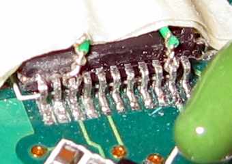
Tying wires to microcontroller pins
Progress so far
I finished building the MON08 programmer circuit last week, so the next step was to run wires from the circuit onto the connection points on the primary PCB(Printed Circuit Board).

At first, I tried soldering 0.25mm wire wrap wires onto the OSC1 and RESET pins on the micro-controller. However, the tip of my soldering iron was far too big (and blunt) for the job, allowing me to accidentally solder the tops first three pins together!
What a mess that was! I spent half an hour scraping it away with the tip of a 1.8mm slotted (flat head) screw driver. Afterwards, I ensured that that the pins were once again unconnected, independent, and free using my trusty continuity tester.
With that soldering lesson well learned, I proceeded to try a different approach: I would literally tie wires onto the pins (see photo above). This was tricky.
I stripped off some insulation from each wire and bent the underlying metal into a crude “U” shaped hook. After much persistence (though mostly luck, it seemed) I was able to loop each wire around its corresponding pin. Then it was just a matter of twisting the excess length of metal around the insulation. Et viola! A metal knot. :-)
Finally, I secured the wires using masking tape so that they don’t move around and accidentally cause the knots to touch the neighboring microcontroller pins.
The road ahead
Now I need to solder 0.60mm wires to the remaining connection points and try to read the micro-controller’s flash EEPROM.
Initially, I thought I would have to install Windows XP on my computer (groan!) just to use the ICS08JBZ programmer software to communicate with my MON08 programmer circuit. But luckily, I found an excellent open source tool called monitor- 68HC08 written by DEMAINE Benoît-Pierre which does the job. This tool’s source code will come in handy if I end up having to crack the microcontroller’s security code by brute force.